W80X Arduino flicker LED
First of all, We will learn how to make LED flicker. This will lay the foundation for our further research. Because you've done this step, I believe that I will have a certain sense of achievement in my future study.
necessity
- 1 x breadboard
- 1 x W801 plate
- 1 X LED The lamp (Or you can not use it, It's on the development board)
- 1 × 330Ω resistance
- 2 × Jumper wire
Wiring diagram
Connect the components on the breadboard according to the circuit diagram, As shown in the following picture. 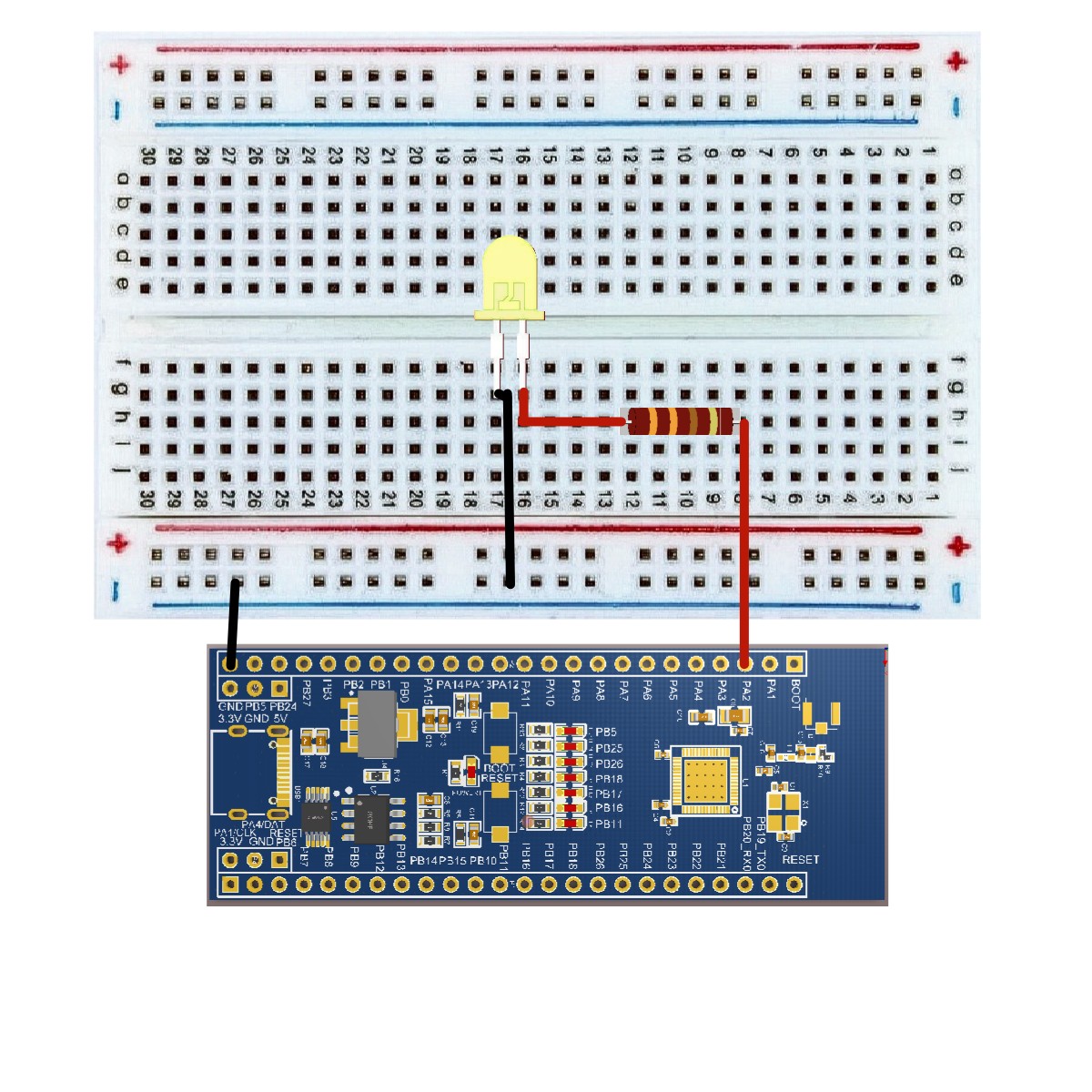
Rough sketch
Open it on your computer Arduino IDE software. Use Arduino Language encodes and controls the circuit. tap "new" Open the new sketch file. Specific configurations are not discussed here. 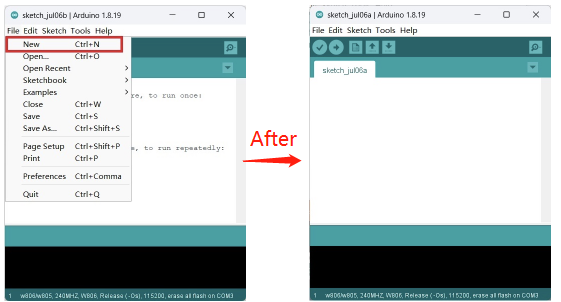
CODE
/*
   Blink
   Turns on an LED on for one second,  then off for one second,  repeatedly.
*/
void setup ()
{
   // initialize digital pin PA2 as an output.
   pinMode (PA2,  OUTPUT) ;
}
// the loop function runs over and over again forever.
void loop ()
{
   digitalWrite (PA2,  HIGH) ;  // turn the LED on  (HIGH is the voltage level)
   delay (1000) ;  // wait for a second.
   digitalWrite (PA2,  LOW) ;  // turn the LED off by making the voltage LOW
   delay (1000) ;  // wait for a second.
}
Code import procedure
First click Verify Verify that the code is correct

Then click Upload A save dialog box is displayed for uploading the code, Edit the file name in the appropriate location and save it

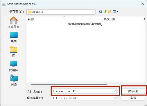
You can also do the following
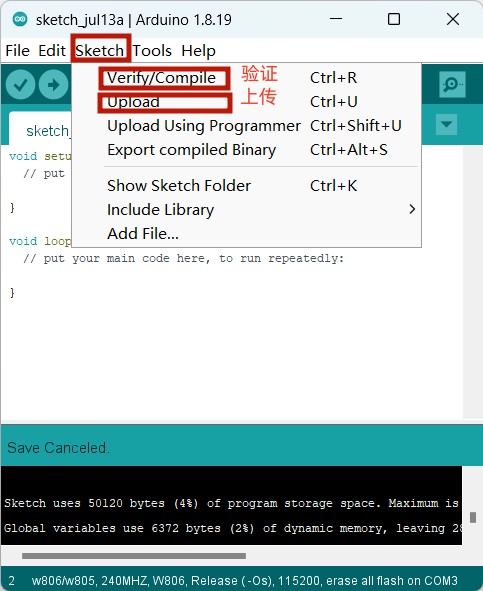
Finally, it takes more than ten seconds to upload, If the following is displayed, it indicates success

Code interpretation
pinMode (PA2, OUTPUT) ; You need to tell W801 It is INPUT still OUTPUT. We can use the built-in "function" pinMode () To do that.
digitalWrite (PA2, HIGH) ; When using pins as output, It can be commanded as HIGH (exportation 5V) or LOW (exportation 0V) .
result
You can see yours LED Open and close. If you don't see the results you want, Make sure you have assembled the circuit correctly, The code has been verified and uploaded to the board.

