Lianshengde W806 and INA226 Equal power meter
@TOC
Context of use:
computer: windows10
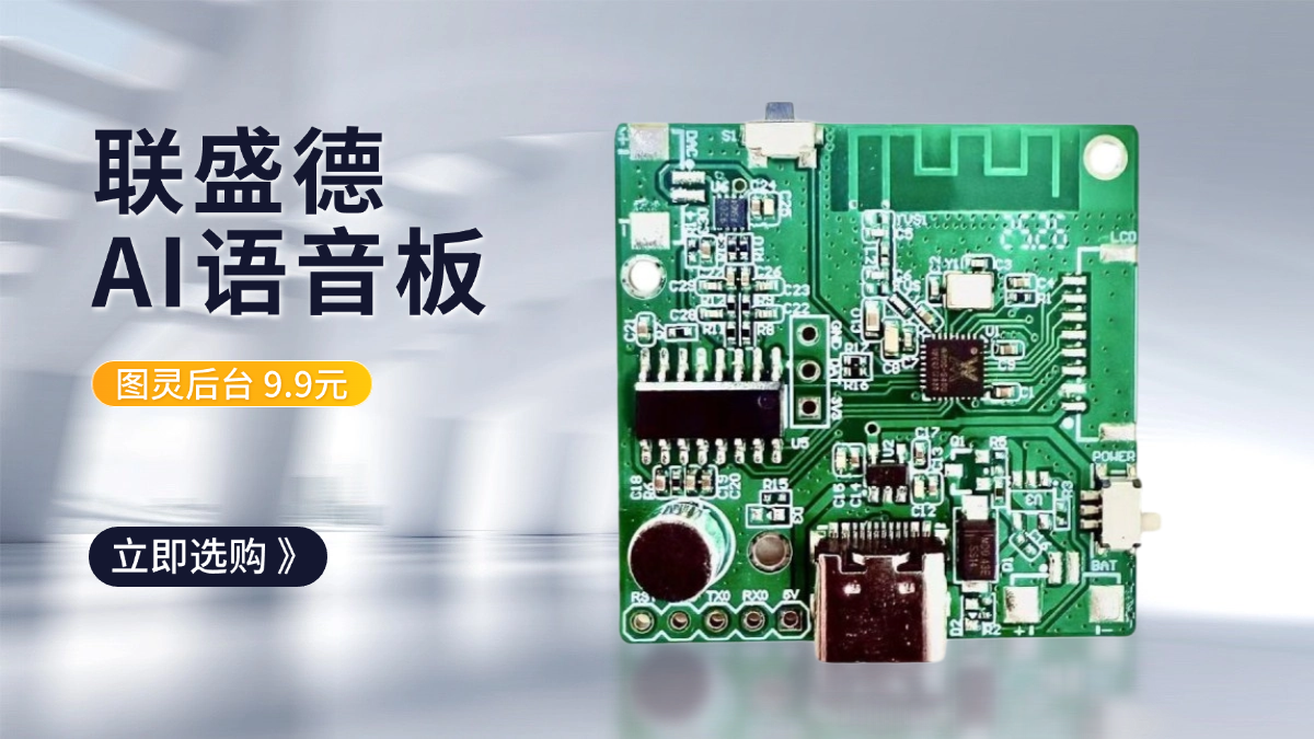
Master control: W806 (240MHZ)
Peripheral acquisition: INA226 (IIC)
Peripheral display: 0. 91 OLED (IIC)
Compilation environment: The Flathead's CDK
Schematic diagram PCB: Lichon EDA, (Totally open source, of course, The link is below, You can change it yourself)
one, Project overview
This is a small design I made on my own time, Those who are interested can have a try, Just practice, Unfortunately, the order was made by mistake, No orders for gay men purple, Excuse the color is a little ugly, Have to make do with.
Graph above: 
It's just a power meter, Also known as the Kulenmeter, What else do you call it, That's not important, The purpose is to collect the external voltage, Electric current, power-consuming. In this count W806 Single chip microcomputer as main control, INA226 As an external voltage current collection IC To do the design. We're not talking about costs or anything, okay, Just think about whether it works, Interested or not. The thing that impressed me most about this board at the time was240Mhz, And the price8. 9, The chip is 5. 9RMB. So don't hesitate to buy it and give it a try, After all, any electronics enthusiast is collecting development boards, Then eat ash.
USB3. 0 port.
Input voltage: 4. 5-36.
Measuring current: 0-5A. PS -- I didn't actually test it, Only did 2A One hour of practical testing, 5A Don't have that condition, Cannot do it.
Master control: W806
reveal: 0. 91OLED (IIC)
Voltage and current: INA226 (IIC)
These two peripherals can actually be used all the way IIC the, But I designed them separately.
two, Hardware design
I put a link at the beginning about the hardware design, If you need to, you can directly take it to modify it, Of course, there are still all kinds of small problems with my drawing board, Point out the problems, Let's revise.
1, Hardware scheme determination
Before the design must be the first choice of solutions, See the picture below for details, Of course, the scheme selection here is also said before, It was my wishful thinking, There is no real consideration of whether the cost is optimal. It's totally my own hobby, Nothing more, So no more details. 
clarify:
1, Download problem
The board design has CH340N, So there's no need for an external connection USB turn TTL the, At the same time, I also connected the reset button directly to the MCU, It should be possible to download and execute the program without pressing the reset key Of course, this is a feature I added later, It wasn't implemented on my first version, This feature is not actually verified, But it's not a problem, Because I saw some guys in the group do it, Normal use, So you can refer to this design.
2, Problems in actual welding:
When welding, When the power supply is not connected to the load, the output voltage is abnormal, Connected to the load is all right, So if you have a reference design please pay attention to this problem.
three, Software design
1, programming
Take into account practical needs, Software design is divided into the following aspects: 
1, Data preservation
This is mainly used to save the time of charging, When there is power consumption, Before timing, After disconnection, the data is saved in flash In the, Until manually cleared, Otherwise it will not be automatically cleaned.
2, Timer timing
One interruption every second, Timing using a variable, Not once a second. I actually tested it, 24 There will be no problem within hours, There is no visible deviation in time, Of course because all I did 24 Hour (s) , So it's not that the longest is 24 Hour (s) .
3, Voltage and current acquisition
I refer to the online tutorial for the program, So don't go into too much detail, I will also attach the source program at the end, Can be downloaded directly. Just the problems I'm having. INA226 Initialization problem: 
The first two functions are fine, It's mainly about the third function CAL value, Be in dispute. 
CAL Be at. h file-defined, I refer to other designs, So in INA226 The first version of the sampling resistor used R100 namely 0. 1 ohm, In practical application, it can only be measured 600 more mA The current of, Finally adopt four 0. 1 Parallel mode, Lower the resistance to 0. 0245 Before normal use. Of course 0. 025 At best, I've tested the sampling resistance 2A The current of, Because the most I have is 2A The load of, No other values were tested low, You can have a try if you have conditions. Tell me how to calculate this value.
First look ina226 the datasheet: (handbook 15 page) 
CAL It is the value written to the register, RSHUNT Is the value of the sampling resistance in this case: 0. 025. And that means you have to figure it out Current_LSB The value of. This leads to other formulas, I have no idea what's going on here, I think I understand a little bit now. Those who are interested can have a look at the original English manual.
INA226_VAL_LSB, It's a voltage register LSB, That is to say a bit It means how much voltage, Take the default 2. 5uV, The maximum bit of the register 0X7FFF = 32767, So the maximum voltage is = 2. 5/1000X32767 = 81. 9175mV. Sampling resistance is 0. 025, The maximum current is = 81. 9175/0. 025 = 3276. 7mA. This is Maximum Expected Current.
Current_LSB = Maximum Expected Current / 32767 = 0. 1.
CAL = 0. 00512 X 1000 / (0. 025 X 0. 1) = 2048
Look out: Some of these formulas/1000 Have no shortage of*1000 Here is the conversion of units.
4, OLED reveal
Just use it OLED reveal. You can read the program.
5, External interrupt keying
Mainly reserved buttons, One of the keys was not used, The other button is used to clear the time.
2, Program flow
It's easier to just look at the picture. 
The program is no longer expanding, You can refer directly to the source code.
four, Closing remarks
This project can only be said for reference, There's a lot of irrationality in the design, You can leave a comment below, There will be time to revise it later.
One might ask about precision, emmm. Hesitate without professional equipment, So you can't give a specific value, I have a galvanometer that I bought, It's the same value as the other two, So you can only be interested in your own slow training.
Let's go to the last picture. 
About the author
Related article
Hot article
Hot issue

Wait for answer
Recommended expert


I used your open source code to make some changes, Want to switch to hardware iic and st7735 Screen,
However, there is a problem in setting the register value
@rain What kind of problem?